
![]()
Involve people having different viewpoints about the system to be forecasted.
Define a uniform and robust vision about the function(s) the system is carrying out.
Method Method = FORMAT methodology
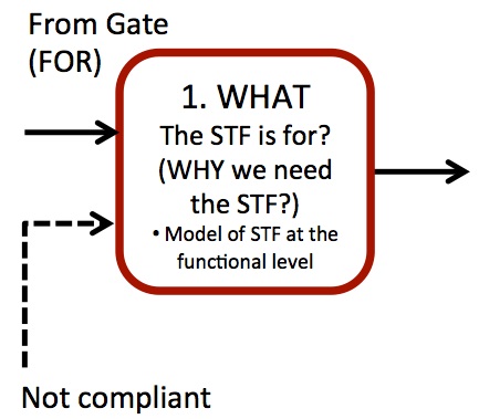
Define the function of the system to be forecasted (STF), highlighting the capability of the STF to transform a given input into a desired output. Produce a clear model of this transformation.
Instructions
- Recall the questions to be answered and the STF as defined in Stage FORFOR = FORmulate . (E.g. the STF is a (a) “domestic oven”; (b) “mixer”, and its function is defined in Step 4 of stage FORFOR = FORmulate ).
A reminder for defining a function (Stage FORFOR = FORmulate ):
- The function should be expressed according to the following template: <the STF> <makes/produces> <outcome>. (e.g.“<the domestic oven><makes><grilled and baked food>; <the mixer><makes><creamy smoothies>”)
- The desired outcomes should be considered as the “OUTPUT” of the function the STF is able to deliver.The output represents what the STF aims at transforming (The OUTPUT in the example is “grilled and baked food” and “creamy smoothie” respectively).
- In the above examples “grilled and baked” or “creamy” is the performance to be achieved through the STF function, for the entities processed by the STF or on which it carries out its function, i.e. “food” and “smoothie” respectively.
- Define the outcomes of the STF qualitatively.
- Keep in mind the entities the STF interacts with to achieve the results the STF has been designed for.
- Answer the question: “What is the system for?”
Note the following:
- The STF strictly requires all the entities associated with producing the desired output. The initial state of those entities should be referred to as the “desired INPUT”. (Desired INPUT: “raw or partially cooked food” and “fruit, milk and ice” respectively).
- The STF requires some other material or immaterial (e.g. energy or information) entities to carry out its function on the desired INPUT. Such entities represent the “required INPUT” for the STF (Required INPUT: “electric energy” (a); electric energy (b)).
- Build a model (EMS or IDEF0 like) of the industrial process the STF belongs to in terms of its function.
- it will be used in the next steps of the project.
- Check ‘example section’ below for a quick overview on how to build the model.
- If you want to add more detailed level.
In case you are dealing with a process-oriented perspective,you might consider worth the analysis to be examined at a more detailed level for the functional description of the STF. Processes are usually considered as sequence of phases (e.g. using specific machinery). Each of them represents an overall function (potentially delivered through other specific, say, sub-functions) whose sequence already represents a functional representation of the process. This requires the overall function (after instructions#1,#2 and#3) to be decomposed in more elementary functions.
The following instructions clarify how to proceed with the functional decomposition:
- The overall modelling approach follows the logic proposed in instructions #1 and #2 also for the sub-functions;
- In order to identify and model sub-functions, consider what the intermediate transformations the OUTPUT undergoes from its “desired INPUT” state; all these transformations highlight the presence of a sub-function carried out on them. The overall logic of functional decomposition is to follow the sequence of intermediate functions the desired INPUT/OUTPUT flow is undergoing
Tips
➔ Double check the consistency of the STF function by applying the following definition of a function: “a function is an action that a subject (STF) carries out on an object (the desired INPUT/OUTPUT) in order to change or stabilize one of its features, characteristics or parameters.”
➔ For a further clarification about the concept of Function and its modelling techniques (e.g. EMS and IDEF0) please refer to the FORMAT White Paper published in May 2013 and to Deliverable 2.2
➔ In case of difficulties encountered in performing the above instructions, identify the overall STF function by answering the following questions: “What is the STF for?” and “What would happen if STF was not existing, or suddenly disappeared while delivering its function”;
➔ The INPUT and the OUTPUT of a function can be considered as material or intangible entities (Refer to the further examples at the end of this step).
➔ Involve people with knowledge about the STF to elicit information about the various contexts where the STF is used. A sensible combination of these contexts may produce a better definition of the STF function.
➔ This functional description is beneficial in the next steps of the FORMAT methodology. In such a step, the analysts are asked to identify competitive or alternative solutions to be considered for a potential substitution of the STF. Therefore, this functional description represents an abstract description of the purpose of the technical system beyond its embodiment and working principle.
➔ When you need to carry out the functional decomposition of the STF from a process viewpoint (instruction #4), consider what the most relevant sub-functions are, with reference to the question of forecast defined along the FOR Stage. A manageable amount of sub-functions for each level of description should be comprised between 2 and 7.
➔ To ease the logic of functional decomposition, example 4 here below shows the functional decomposition of the process of “cooking pasta” that, by itself, represents a function (see A-0 Context diagram). That example is presented with the IDEF0 logic. The A-0 Context diagram also clarifies how the arrows should be interpreted with reference to previous examples. The 1st level functional decomposition is presented in the A0 model as the sequence of three sub-functions: Preparation (further detailed in A1); Cooking (A2); Plating up (A3). The background colour of each Ax model reflects the links among the models.
➔ If you are already familiar with the System Operator logic (Deliverable 2.3) or have already carried out a study with the FORMAT methodology, it could be beneficial to start organizing information and data according to that framework. This will allow you to record the information in a unique model and speed up the activity along the whole stage (especially step M5). The example #5 shows how to start inserting the information of this step inside the System Operator model. The content is the same as proposed along example #4.
Suggested reading
Becattini N, (2013) On the definition of functions for the identification of system requirements. FORMAT Project White Paper May 2013, available at http://www.format-project.eu/deliverables/white-papers
Becattini N, (2013) PRODUCT AND PROCESS MODELLING – STATE OF THE ART UPDATE – FORMAT Deliverable 2.2 – pp. 18-34 –http://www.format-project.eu/deliverables/public-reports-and-white-papers/deliverable-2.2/view (it includes full references about IDEF0 and EMS).
Pahl, G., Beitz, W., Feldhusen, J., & Grote, K. H. (2007). Engineering Design: A Systematic Approach (Vol. 157). pp.31-38 – Springer.
Example
Example 1a-b. STF Processing Materials
- The STF is the (a) “domestic oven”;(b) “mixer”;
- The OUTPUT is “grilled and baked food” (a); “creamy smoothie” (b);
- The INPUT for the function is:
- Desired INPUT: “raw or partially cooked food” (a); “fruit, milk and ice” (b);
- Required INPUT: “electric energy” (a); electric energy (b);
- The diagram of the functions for (a) and (b) is presented in Figure 1.
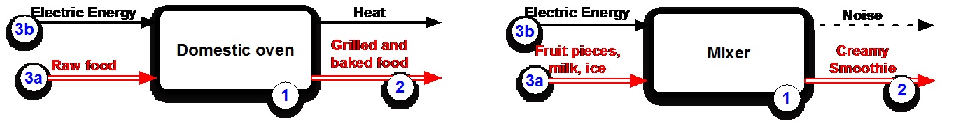
Figure 1. EMS functional diagram of a domestic oven (left) and a mixer (right). The examples present also real OUTPUTS, even if not necessarily desired.
Example 2. STF Processing Energy
- The STF is the “photovoltaic panel”;
- The OUTPUT is “electric energy flow”;
- The INPUT for the function is:
- Desired INPUT: “solar radiation”;
- Required INPUT: none;
- The diagram of the function is presented in Figure 2.
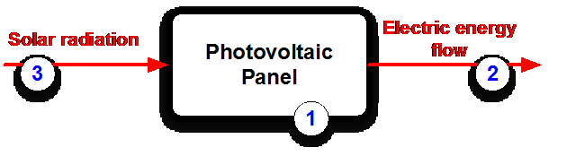
Figure 2. EMS diagram of a photovoltaic panel (STF processing energy)
Example 3. STF Processing Signal (Intangible Entity)
- The STF is the “digital audio compression algorithm”;
- The OUTPUT is “portable file of adequate audio quality”;
- The INPUT for the function is:
- Desired INPUT: “big size Hi-Fi audio recording”;
- Required INPUT: “electric energy …”;
- The diagram of the function is presented in Figure 3.
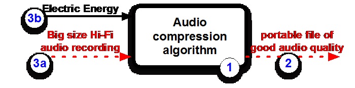
Figure 3. EMS diagram of an audio compression algorithm (STF processing signal)
Example #4: Process modelling – Cooking Pasta
- The STF is the “process for cooking pasta”;
- The OUTPUT is “Plated spaghetti”;
- The INPUT for the function is:
- Desired INPUT: “Raw spaghetti, Water, Salt”;
- Required INPUT: “Heat, Pot, User, Colander, Scale”;
- The diagram of the function is presented in Figure 3. It also includes the real outputs include “Hot salty water” and as controlling elements for the process, doses and timing have been made explicit.

Figure 4. The IDEF0 A-0 Context Diagram for the process of cooking pasta. The model includes circled numbers to show the link with the modelling technique proposed in the instructions. The orange background colour highlights the connection with the A0 model, which represent a first level functional decomposition of the process.
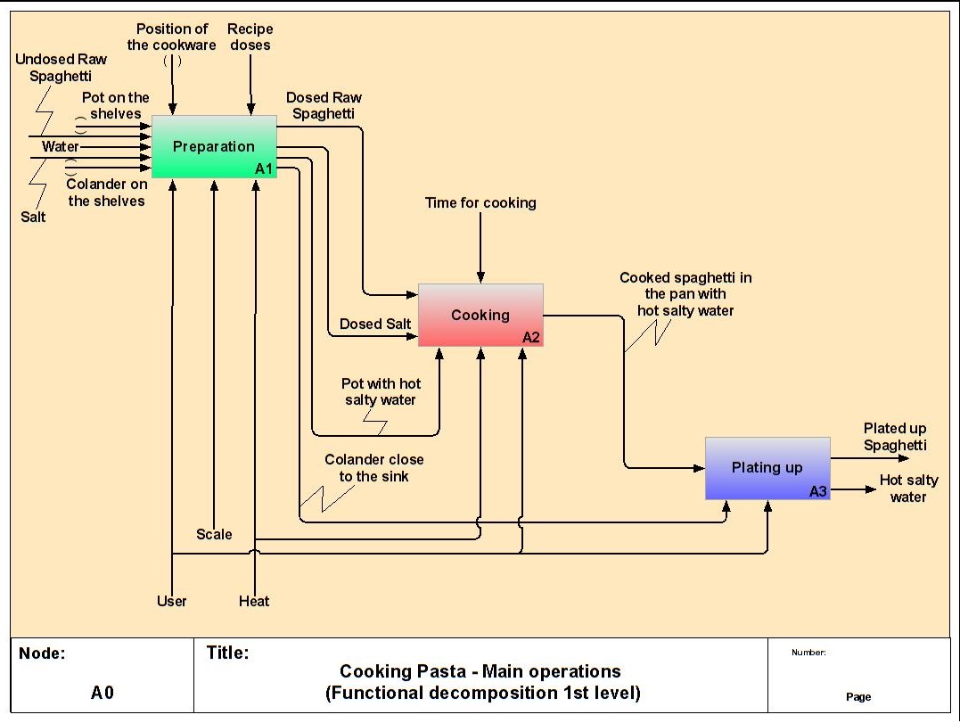
Figure 5: The first level functional decomposition of cooking pasta. A1, A2, A3 are collared consistently with the colour background of the next models.
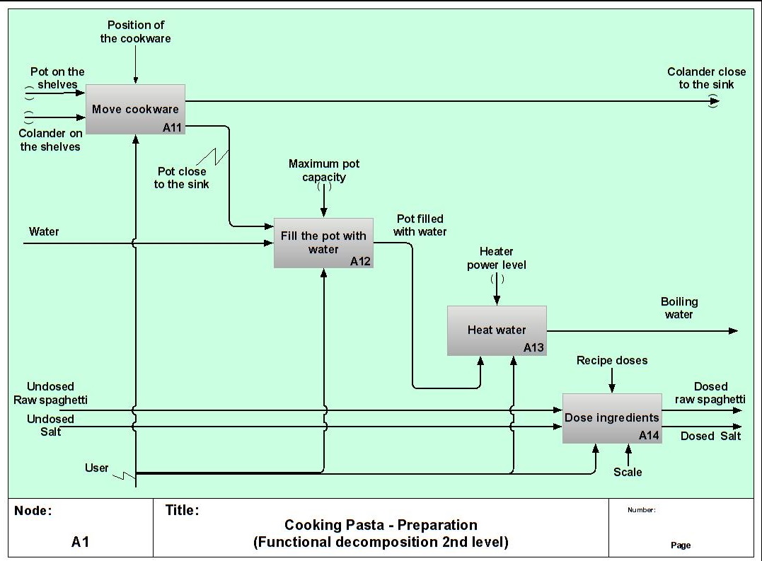
Figure 6. A more detailed perspective about the function characterizing the overall stage of Preparation
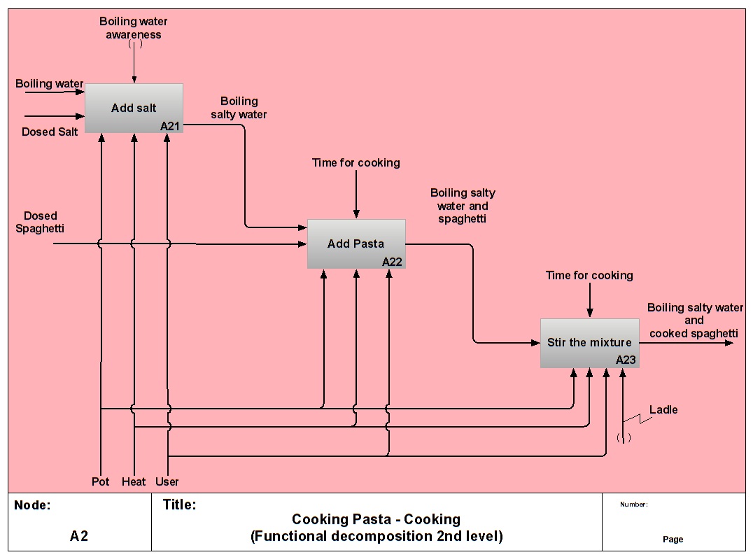
Figure 7. A more detailed perspective about the function characterizing the overall stage of Cooking
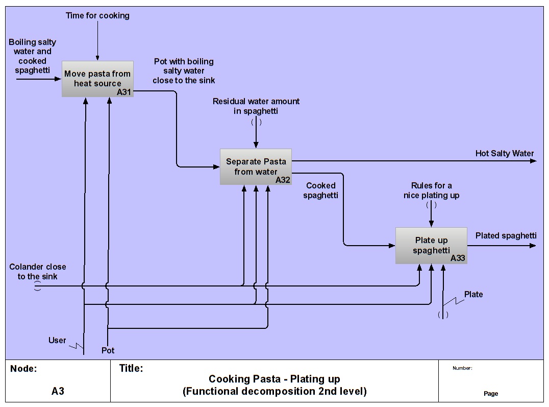
Figure 8. A more detailed perspective about the function characterizing the overall stage of Plating up.
Example #5: Integration of a Functional model within the System Operator framework.
This example shows how to organize the information or formalized knowledge according to the System Operator logic. Figure 9 shows a 3×3 matrix, where each cell corresponds to specific content in space (vertical axis) and in time (horizontal axis). The content defined along this step (M1) pertains to the function of the whole STF, which has to be intended as the system corresponding to the current state of the art.
The function of the STF, therefore, is a content that pertains to the system level. Being a description of the current STF, it should be placed in the cell corresponding to the present time frame. Accordingly, an excerpt of Figure 4 is placed inside the “System level – Present” cell.
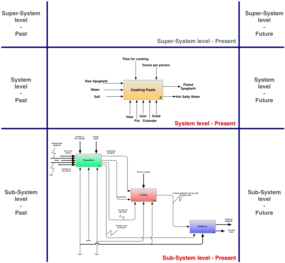
Figure 9: Example to show how the content developed along this step can be organized consistently with the System Operator logic.
In case you decide to further detail the investigation of the main function to a model where sub-functions become explicit, your analysis is focusing on the sub-system level. The functional decomposition of the STF, therefore, pertains to the “Sub-system level – Present”. An excerpt of Figure 5 has been accordingly placed in the related cell.
Please note, that you may also opt to characterize the STF in terms of its components or parts. This decomposition, being structural instead of functional, still pertains to the Sub-System level.
v.2