
![]()
List the problems of system to forecast (STF) and identify limiting resources that are related with them.

Method
Identification of problems about the STF is another way to describe the STF. Problems should be identified from the description of the system in Stage M (e.g. from results of System Operator); more precisely the team should reflect on the conflicts between drivers and barriers. Every problem is connected to a number of limiting resources. A limitation in the availability of a critical resource leads to a problem of an unfulfilled need. Identification and study of limiting resources and their dynamics clarifies the future changes about STF and its contexts.
Instructions
- What are the most critical problems?
In order to collect the list of problems, consider the results of stage M. Problems are collected for system, sub-systems and super-system levels using structured interview with specialists about STF. First, the only titles of problems are collected for building a consensus and consistent list of problems.
- Reformulate set of problems.
Second, the collected list of problem titles is disclosed using the contradiction model or using the simplified template: “How to <required action> when <the real-case limits>?”
- Identify limiting resources for each listed problem (contradiction).
Third, for every problem the limiting resources (e.g. time, space, substances, energy, etc.) are identified using practical evidence. The unit of measure has to be allocated for each limiting resource.
- The developed outcomes are combined in a table with four columns: (1) problem number; (2) description of problem in accordance with simplified template or using the contradiction model; (3) limiting resources; (4) measurement units.
- Identify a subset of the most critical problems among the collected ones with help of users of forecast. Expert judgment is applied for identifying the set of most critical problems.
Tips
- When collecting list of problems, first focus on the main system to forecast. Meanwhile, the analysis of alternative technologies (collected within Stage M) can be useful for completing the list of problems. The study about alternative systems helps to enlighten hidden problems and peculiarities, which are not evident due to professional biases.
- Techniques applied for problems identification should be operational and not time consuming. Models for description of the system (e.g. System Operator) help in guiding a systematic study in search for problems.
- Getting into details in problem description may cause a tendency to revise the models built in Stage M. However, this is likely to produce delays in the fulfilment of the project and it could imply to miss the big picture. Furthermore, for a matter of coherence, changes to Stage M elements should be avoided once the gate M is closed.
- Concept of limiting resources is based on the assumption that each problem is linked with consumption of a resource e.g. time, data, energy, substance. Such a resource is either limited or non-existing in particular conditions, hence a need cannot be satisfied and a problem appears.
- When defining limiting resources, make them quantifiable and measurable. Measure is meant here as a unit in which a resource is quantified. Expression of specific values would be an advantage.
- How to work with Contradiction models (optional):
Contradiction is a way to represent a problem. Contradiction provides a structure that facilitates the construction of a problem’s model. A problem expressed in the form of a contradiction consists of the following elements (the following capital letters in brackets refer to Figure 1): feature (B) of an object (A) should assume a certain value (C) so as to achieve a desired outcome R2(+); nevertheless, the value (C) of feature (B) also implies some unwanted results (R1-). On the contrary, the feature (B) might assume an opposite value (D) that brings the latter to a desired state (R1+), but this implies an unwanted variation of the former R2(-). The opposite values (C) and (D) cause a conflict. Both positive and opposite values bring desired (+) and undesired (-) results. A single contradiction contains two of these results: R1 and R2 (Figure 1).
A contradiction is formed by describing one state of a system, for one value of a feature with an explanation of the positive R1(+) and negative R2(-) effects. Next, the opposite state of a system, for an opposite value of a feature, is described with an explanation for the positive R2(+) and negative R1(-) effects. The problem is to obtain both the desirable results R1(+) and R2(+) at the same time, although they appear at opposite values (C) and (D). A solution to a problem expressed in this way goes beyond the trade-off (a compromise between the two values).
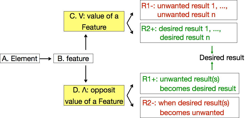
Figure 1. Model of a contradiction with A, B, C, D, R1, R2 elements referred to in the text.
Each problem from a list of problems has to be transformed into a contradiction. Using a model for a contradiction expression presented on Figure 1, one usually starts with declaration of R2(+), a first desired result. Desired result is usually clear for a current situation. R1(-) is then realized as a negative result presently observed. Then an opposite part of contradiction should be filled with R1(+) as an opposite result to the unwanted R1(-) declared earlier. It is allowed to enter more than one desired or unwanted result into a particular box.
It is a suggested method that will help you better understand problems of a system to be forecasted. Formulation of a contradiction helps also in better definition of a problem formulated from the original expression, for instance of an unsatisfied need.
Suggested reading
[1] Altshuller, G. S., & Williams (transl.), A. (1984). Creativity as an Exact Science: The Theory of the Solution of Inventive Problems. New York: Gordon and Breach Science Publishers.
[2] Becattini, N. (2013). Product and process modelling – state of the art update (p. 59). Milan. Retrieved from http://www.format-project.eu/deliverables/public-reports-and-white-papers/deliverable-2.2/at_download/file
[3] Cascini, G. (2012). TRIZ-based Anticipatory Design of Future Products and Processes. Journal of Integrated Design and Process Science, 2012, Vol-16 (3), p. 29-63.
[4] Kucharavy, D (2014). Contradictions in the domain of technological forecasting. (p.9) Milan. Retrieved from http://www.format-project.eu/deliverables/white-papers/november-2014-contradictions-in-the-domain-of-technological-forecasting/at_download/file
[5] Kucharavy D. and R. De Guio (2008) Technological Forecasting and Assessment of Barriers for Emerging Technologies, IAMOT 2008. Dubai, UAE, p. 20
[6] Kucharavy D., R. De Guio, L. Gautier, and M. Marrony (2007) Problem Mapping for the Assessment of Technological Barriers in the Framework of Innovative Design, in 16th International Conference on Engineering Design, ICED’07.
Example
Project “packaging” aims at forecasting the future of materials for packaging home appliances. Previous stage, stage M M = Modelling delivered a description of a packaging system. A single description is recalled here in order to give a starting point for the current step of Stage A A = Act . System completeness model describes elements of a system connected in order to deliver a function performed by a system. “Every technical system should consist of four components: engine, transmission, control unit and working unit”(Salamatov, 1999).Elements of a system are predefined as: incoming energy, conversion machine, transmission machine, tool, product and control, as shown in Figure 2. The description of a system is delivered by describing each of the predefined elements with respect to the studied system.
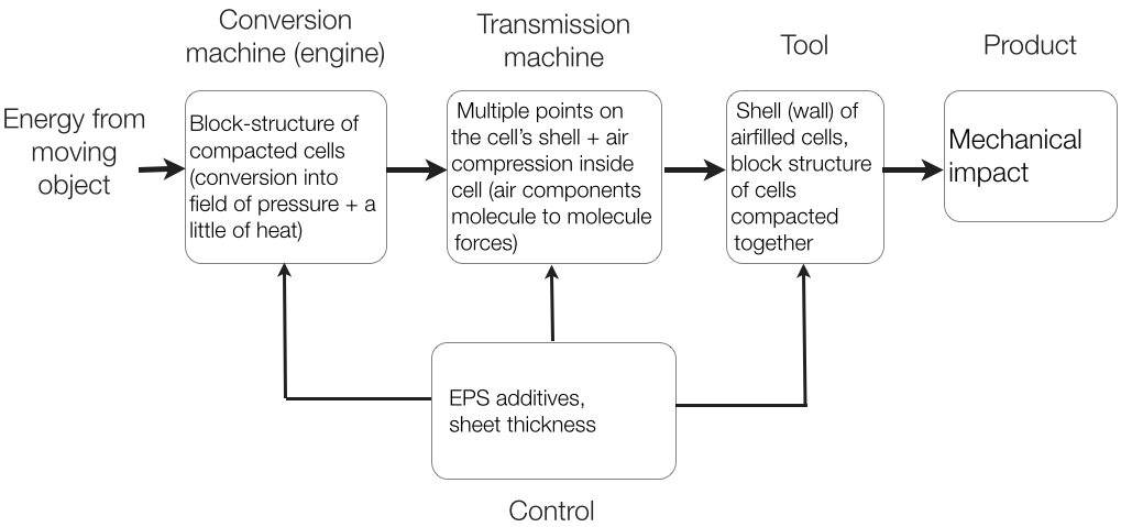
Figure 2. Model using a Law of system completeness described for ‘packaging’
Figure 2describes a ‘packaging’ system at work when absorbing a shock. In this case a packaging system is made of EPSEPS = expanded polystyrene (expanded polystyrene) and plastic film. The main function of packaging was defined in Stage M Add a Tooltip Text as “to dissipate kinetic energy during logistic operations.” The problems identified following the description of the system shown in Figure 2:
- Vector of energy hitting packaging may have different direction
- Abrasive forces
- Disintegration of EPS EPS = expanded polystyrene structure due to impact above the strength threshold of the structure
- Nature of the striking object e.g.: dust, humidity, water, dirt, clasping plates of a “forklift”
- EPS is difficult to recycle and is not currently recycled in large scale.
Alternative way of expressing the same problems is to formulate them as unsatisfied needs:
- Packaging should dissipate kinetic energy imparted from different sides of a packaged product
- Packaging should dissipate energy due to abrasive forces.
- We need packaging to protect a packaged product from multiple impacts, not only from the first. It means that packaging once impacted or maybe even destroyed should still retain its protecting properties.
- It is required that packaging also protects the appliance from dust, humidity, dirt and withstands forces applied by regular logistic processes like clasping plates in a forklift.
- There is a need for a recyclable packaging.
Problems identified when studying alternative technologies. Example of alternative technology: cardboard profiles, cardboard box.
- Impact of humidity – it is required that packaging is resistant to humidity and even water e.g. rain during logistic operations, water spilled on the ground in storehouse.
- Need for compression stripes – it is desired to have as few additional elements as possible.Addition of plastic compression stripes adds to number of packaging’s components.
Limiting resources (identify and declare measureable variables)
- Size of an area of packaging that is the most frequently hit i.e. edges, top, bottom [m2]
- Size of an area of packaging that is exposed to abrasive forces [m2]
- Thickness of packaging [m]
- Sizeof a standard transportation container (width x height x length) [m]
- Force applied during test on packaging [N]
- Force applied by clasping plates on forklift [N]
- Weight load during storage [kg]
Contradiction Following example provides a contradiction built for one of the problems – a problem with the resistance of packaging. It is required that packaging be resistant to damage, but it is also required that the packaging is easy to open. In the form of a contradiction, a problem is expressed as follows. The packaging needs to have high resistance in order to provide high energy dissipation, but then it is rigid and difficult to open. The packaging needs to have low resistance in order to be easy to open, but energy dissipation gets lower.
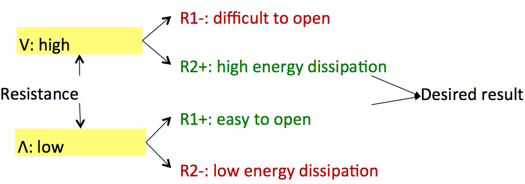
Figure 3. Contradiction for resistance of packaging
v.2