
![]()
Identification of direction of technological development based on historical evolution of the STFSTF = System to be forecasted .
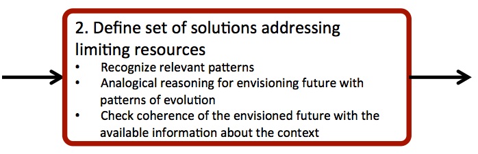
Envisioning the characteristics of future solutions for the STFSTF = System to be forecasted .
Method
Analyse the history of the STFSTF = System to be forecasted (or some of its phases) and recognize the related evolutionary patterns according to the technological, environmental economic and social trends (STFSTF = System to be forecasted trends). Use this pattern analysis to project what will be the future developments of the STF.
Instructions
- Recall the questions of forecast from the FOR stage
- Also, recall the (System Operator analysis) results of Step 5 in Stage M.
- Think about the scope of your analysis with reference to the questions of forecast. Consider if it is more important for that purpose to focus on the whole STF or on some of its critical and more promising phases prior to evolution. In case you need to focus on a specific phase of the process carried out by the STF, or on a specific subsystem. Answer the following questions in order to highlight the most relevant process phases:
- What are the specific operations, parts, etc., generating the bottlenecks?
- What are the reasons preventing the adoption of the most relevant alternative technologies?
- Recognize the patterns driving the evolution of technical solutions for the functions or phases defined in Instruction #3. In order to help with the pattern analysis, follow these instructions:
- Browse the system operator on the time axis at the same hierarchical level.
- Compare the evolution of specific features across time screens, in order to track how the STFSTF = System to be forecasted or its parts or the contexts have evolved.
- Use the above information to analyse the reason for the evolution of the STFSTF = System to be forecasted along those paths.
- The reasons behind the evolution and the way evolution occurred should shed some light on the relevant patterns driving the change of the STFSTF = System to be forecasted and its alternatives.
- Analyse the STFSTF = System to be forecasted using models to create an envisioned future scenario. Develop this analysis by analogical reasoning. The model of the STFSTF = System to be forecasted has to help you to recognize patterns and directions for its evolution.
- Build a model of a Minimal Technical System (TRIZ Law of Engineering System Evolution#1- Deliverable 2.2) for each of the functions selected in Instruction #4.
- Compare the trends emerged from the evolution of the technical systems under investigation with general patterns in technological, economic, environmental and social domains (TEESTEES = Technological, Economic, Environmental and Social trends).
- Match the technical system evolution, through reasoning –by- analogy, with the trends and understand which evolutionary stages have already occurred, which are now characterizing the subject of the investigation and those that still have to appear.
- Summarize the available opportunities for further technological development i.e. all those evolutionary stages that have not already emerged for the system under investigation.
- Check coherence of the envisioned future solutions by comparing the list of problems and beneficiary demands.
- Recall the list of problems from the previous step in Stage A and, if needed, clarify which are the main demands behind those problems.
- Select the further directions of evolution for the system under investigation by excluding those that are not addressing the above demands
- Derive some conclusions and recommendations for beneficiaries by considering the potential benefits of the envisioned solutions.
Tips
➔ The model of Minimal Technical System (MTS) is presented in Deliverable 2.2. In brief, you can build the model following these instructions:
- Recall the desired OUTPUT from the functional description of the STFSTF = System to be forecasted (Step 1 in Stage M).
- Identify the Tool, i.e. the entity which interacts directly with the object of the function thus producing the desired OUTPUT;
- Determine which properties characterize the capability of the Tool to deliver the function to the desired OUTPUT;
- For each of the identified properties, define the Engine, i.e. the element from which the property derives;
- Complete the model of the minimal technical system, by adding the transmission from the Engine to the Tool, the control and its interactions with the other subsystems and the external supply of the Engine.
➔ A comprehensive set of technical evolutionary patterns is provided by TRIZ (Cascini, 2012); in Cascini et al. (2009) an operational procedure to map the evolution of the STFSTF = System to be forecasted through the TRIZ patterns is provided.
➔ Analogical reasoning shall involve also non-technical trends, such as social and economic mega-trends (e.g. Rosen, 2000).
➔ Once you have identified the relevant evolutionary trends and you have envisioned by analogy possible qualitative scenarios for the STFSTF = System to be forecasted , it is advisable to colour the map to increase its readability; e.g. past and current solutions could be coloured in red, non-commercialized but recognized concepts (e.g. from patents, articles, publicly funded projects etc.) could go yellow, while green characterizes free space for R&D.
Suggested reading
Cascini, G., Rotini, F., and Russo, D. (2011) Networks of trends: Systematic definition of evolutionary scenarios. TRIZ Future Conference 2008, Procedia Engineering,Vol-9,p. 355-367.
Cascini, G. (2012) TRIZ-based Anticipatory Design of Future Products and Processes. Journal of Integrated Design and Process Science, Vol-16 (3), p. 29-63.
Nikulin, C., Graziosi, S., Cascini, G., and Stegmaier, R. (2013) Integrated Model for Technology Assessment and Expected Evolution: A Case Study in the Chilean Mining Industry. Journal of Integrated Design and Process Science, Vol-17(4), p-53-80.
Rosen C. (2000) World Resources 2000-2001 People and Ecosystems: The Fraying Web of Life, Elsevier Science, 389 pages.
Something about MTS modelling: http://www.format-project.eu/deliverables/public-reports-and-white-papers/deliverable-2.2/view
Becattini, N. (2013). Product and process modelling – state of the art update (p. 59). Milan. Retrieved from website.
Example
The following example refers to the copper mining process. The process is typically made up of the following steps:
- Drilling, blasting, cutting, and excavating
- Ground control
- Loading and hauling
- Materials processing
(for a more detailed description see also www.mining-technology.com).
In the fourth step, the ore is transferred to gyratory crushers that reduce its size. This crushed ore is then conveyed to the mill grinding circuit.
The size and power production of the mill has increased significantly since its inception in the 1920’s, currently reaching over 40 ft in diameter and processing about 2000 ton/h. It also involves the largest percentage of operating costs and extremely time-consuming maintenance operations in a mining company (approx. 200-hours a year). Besides, the maintenance activity requires manpower, resources and several days of detention: under normal operating conditions in a plant that processes 100 kton/day, the outage cost is approximately US$ 270,000 per day (for further details see also [5]). A mill can be considered as one of the most critical technologies of the mining process: it respectively influences its upstream and downstream activities and the overall productive capacity of the plant (in copper mining).
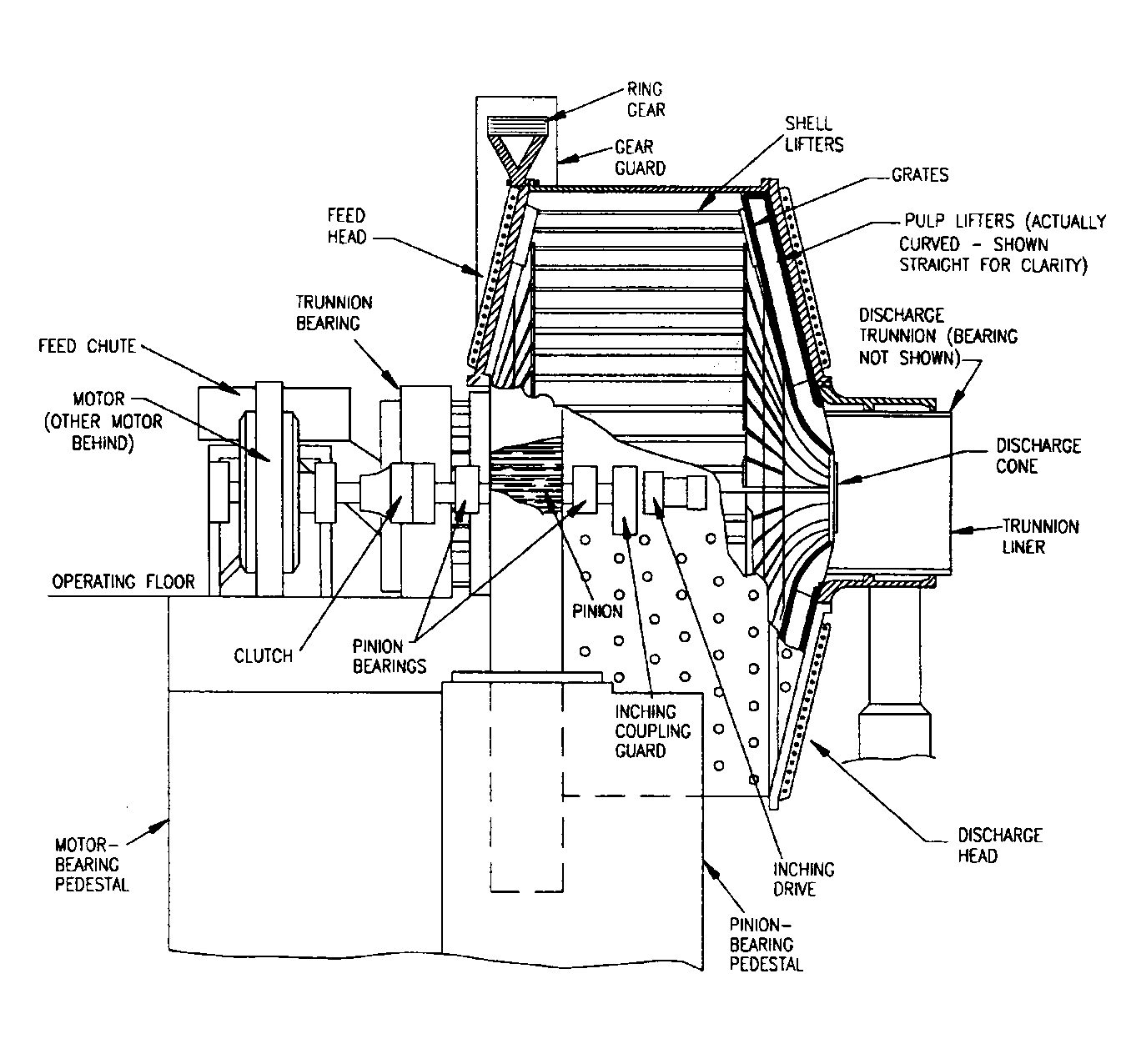
Figure 1: The general mining mill elements.
The main useful function of a mill is to perform the <grinding> process. This function is realized by means of the following sub-functions (Figure 2):
- Regulate Ore Quantity. It controls the quantity and the flow of mineral and water inside the mill. The belt conveyors deliver the ore to the mill. The feed rate of the mill depends on the horsepower available to rotate the mill and on the weight the mill shell can support (see also www.technology.infomine.com).
- Decrease Ore Size. It is the breaking action done by grinding the ore into fine powder. In the mill, the dry ore is combined with water and steel balls. The mill is equipped with lifters that raise the load during the mill rotation. The tumbling action causes the larger ore pieces and steel balls to grind the ore into fine particles. The control board of the mill’s electric motor regulates the RPM and thus the mill shell rotation. The plates protect the internal part of the mill and are fixed to the mill shell. The load itself generates a mechanical pressure on the mill internal surface.
- Separate Ore. It is the activity of separating particles according to their sizes. Usually the mechanical pressure generated by the load is used to force the material passing through a grid (i.e. the screening surface), whose dimensions depend on the desired size chosen for the ore particles.
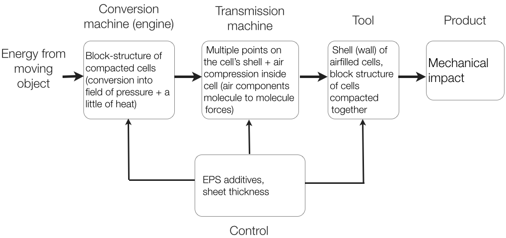
Figure 2: The chunked model of the industrial process under investigation and Minimal Technical System model for each functional phase.
A brief investigation was performed in order to evaluate the sub-functions consuming the highest amount of resources relevant for the milling process; a qualitative evaluation was performed for each sub-function in order to understand the most critical functional phases (table 1).
Table 1: Qualitative evaluation for the identification of the most critical functional phases in the mill process
| Resource | Regulate ore quantity | Decrease ore size | Separate ore |
| Maintenance time | Low | Medium-high | Low |
| working lifetime | High | Medium | High |
| Energy consumption | Low | High | Low |
| Thickness due to the wear/friction | High | Medium | Low |
The most critical functional phase for the industrial process is the functional phase “decrease” (Table 1), because it requires the largest maintenance time and the highest energy consumption. More specifically, the maintenance involves the elements of the mill embedded in the internal cavity that is covered by plates/lifters and that are designed to lift the load (i.e. the ore mixed with water and balls) during the mill rotation (Figure 1). Through the rotation of the mill, the load undergoes lifts and falls, with a continuous crushing effect (see also Weir Slurry Group, 2009 [6]). Besides, the internal plates have also another function, i.e. to protect the internal shell of the mill from the impacts generated by the rotating load. For these reasons, a failure occurring in these plates/lifters can determine the stop of the grinding process and the breakage of the mill-shell. In this case study, “plates/lifters” are the elements of the technical system (i.e. the mill) that will be analysed.
The evolutionary analysis was made by following the procedure described in (Cascini et al, 2008). Then, in order to check the meaningfulness of the envisioned trends, a patent search was performed focusing both on the whole system (i.e. the mill) and on the subsystem/tool (i.e. the plates/lifters). Figure 3 shows the plate/lifter evolutionary analysis. According to the approach followed in this case study, each invention (patent) is assigned to one representative TRIZ pattern of evolution. The red boxes represent inventions already patented (an indication of the patents available is provided), while green ones represent free research/design spaces and thus opportunities for new inventions.
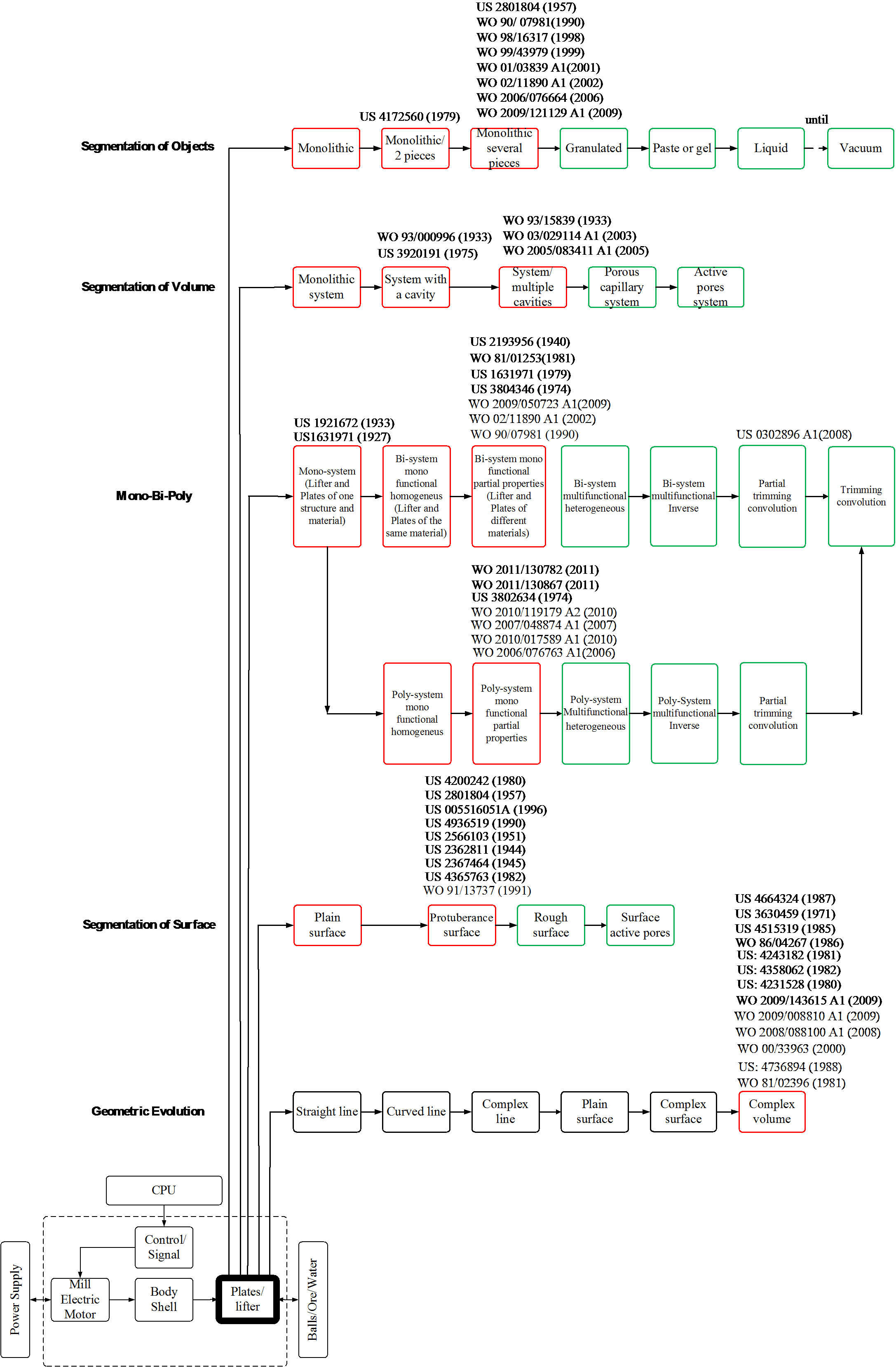
Figure 3: The plate/lifter evolutionary analysis.
As a result of the study, the inventions clustered in the Segmentation of Object pattern are related to the physical separation of the plates from lifters (preserving the same functionality). The trend suggests increasing the degree of segmentation, by reducing the size of the parts. The objective is to reduce the maintenance time (e.g. the substitution of the broken plates is easier when their size is smaller) and to increase their working life (i.e. the amount of impact energy that each plate has to support is lower). According to the number of green boxes available, further improvements are still possible. The objective is to reduce the maintenance time (e.g. the substitution of the broken plates is easier when their size is smaller) and to increase their working life (i.e. the amount of impact energy that each plate has to support is lower).
In case of the Segmentation of Volume pattern, the creation of cavities allows to reduce the friction effect. Within the Mono-bi-poly trend are clustered those inventions that propose various implementing solutions for the plate/lifter in order to improve its technical potential (i.e. wear damage, shock absorption). As before, considering the number of green boxes available, this trend has to keep evolving, creating a combination of different parts with different materials, but having more functionalities. The inventions belonging to the Segmentation of Surface at subsystem level are focused on finding different configurations, in terms of plate/lifter distribution over the shell surface (e.g. the orientation of the plates) in order to increase the productivity of the mill. The Geometric Evolution pattern focuses on optimizing the configuration of the plates/lifter (in terms of geometry and volume), in order to provide a better movement to the load and decrease the damage due to the impact of the load on the plates (e.g. US4736894, 1988 [8]). This pattern is completely saturated.
By applying the analogy formalized with TRIZ trends and patterns, different sets of solutions have been identified for the development of the grinding function. The solutions are summarized in the following bullet list:
- More tools or fields can be added, even if it is hard to figure out a meaningful one; as for example, by adding a chemical or biological substance which can react with the ore and water in order to improve the grinding process.
- Harmonization of the impact among the balls, ore and plates; this can also help to reduce the number of damaged plates and the energy consumption of the decreasing phase.
- Development of new plates and lifters with new material properties (e.g. by using Superelastic materials to reduce the impact).
Reference example:
[6] S.A. P. M. (2006). Manual General de Minería y Metalurgia. Antofagasta: Portal Minero Ediciones.
[7] Weir Slurry Group, (2009) Mill circuit pum manual, Report, available on-line at www.weirminerals.com, last accessed July 2013.
[8] Patent n° US4736894 (1988), Grinding mill lining system
v.2